Tel:+86-0572-2926332 / 2926337
E-mail:[email protected]
 English
 简体中文
简体中文Silicon Nitride Stopper Tube: What It Is, How It Works, and Why Foundries Rely on It
2026.04.01
Content
- 1 What a Silicon Nitride Stopper Tube Does in a Metal Casting System
- 2 The Casting Process That Makes a Silicon Nitride Stopper Tube Indispensable
- 3 Why Silicon Nitride Is the Right Material for This Application
- 4 Silicon Nitride Stopper Tube vs. Competing Materials: A Practical Comparison
- 5 Critical Dimensions and Specifications When Selecting a Silicon Nitride Stopper Tube
- 6 Installing a Silicon Nitride Stopper Tube Correctly
- 7 Signs That a Silicon Nitride Stopper Tube Needs to Be Replaced
- 8 Getting the Most From Your Silicon Nitride Stopper Tube Investment
What a Silicon Nitride Stopper Tube Does in a Metal Casting System
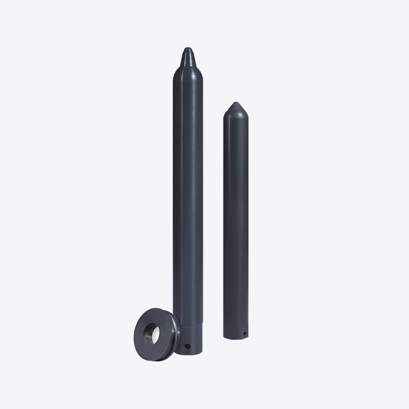
A silicon nitride stopper tube is a precision ceramic component used in low-pressure die casting (LPDC) and other controlled-flow casting processes to transfer molten aluminum from the holding furnace into the die cavity. In a typical low-pressure casting setup, the stopper tube — sometimes called a riser tube or stalk tube — is submerged vertically into the aluminum melt inside a sealed pressurized furnace. When inert gas pressure is applied to the furnace atmosphere, the molten metal is forced upward through the tube's internal bore and into the die above. When the casting cycle is complete and pressure is released, the metal column in the tube falls back into the furnace, ready for the next cycle. The tube therefore acts as the sole physical conduit between the molten metal and the casting tooling for the entire production run.
The material demands on a component performing this role are severe. The tube must resist the chemical attack of molten aluminum at temperatures between 680°C and 780°C, survive thousands of pressurize-and-release thermal cycles without cracking, maintain dimensional stability so the seal at the furnace cover plate remains gas-tight, and introduce absolutely no contamination into the metal that flows through it. Silicon nitride (Si3N4) satisfies all of these requirements more completely than any other commercially available material, which is why it has become the standard stopper tube material in quality-conscious aluminum foundries worldwide.
The Casting Process That Makes a Silicon Nitride Stopper Tube Indispensable
To appreciate why the stopper tube is such a critical component, it helps to understand the low-pressure die casting process in more detail. Unlike gravity casting, where molten metal is poured into a mold from above and fills by its own weight, low-pressure casting applies a controlled upward pressure — typically between 0.3 and 1.5 bar — to push the melt smoothly and consistently into the die from below. This bottom-fill approach means the metal rises through the tube and enters the die at a controlled velocity, dramatically reducing turbulence, air entrainment, and the oxide film inclusions that turbulent filling creates.
The quality advantage of this approach is well established: automotive wheels, structural suspension components, cylinder heads, and other safety-critical aluminum castings are predominantly produced by low-pressure die casting for exactly this reason. But the process's quality advantage is entirely contingent on the integrity of the stopper tube. A tube that leaks at its flange seal allows pressure to escape, causing inconsistent fill rates and incomplete fills. A tube that reacts chemically with the melt introduces inclusions that compromise the mechanical properties of every casting produced. A tube that cracks mid-production can release ceramic fragments into the metal — a contamination event requiring furnace shutdown, full melt inspection, and potentially the scrapping of a significant volume of metal. Silicon nitride stopper tubes prevent all three of these failure modes more reliably than competing materials.
Why Silicon Nitride Is the Right Material for This Application
Silicon nitride's dominance in the stopper tube application comes from a specific convergence of material properties that individually address each of the major failure mechanisms that affect competing tube materials. No single property explains the preference — it is the combination that makes Si3N4 uniquely suited.
Non-Reactivity With Molten Aluminum
Molten aluminum is chemically aggressive toward many refractory materials. It reduces silica (SiO2) readily, reacts with carbon to form brittle aluminum carbide (Al4C3), and attacks boron nitride under certain temperature and alloy conditions. Silicon nitride does not participate in any of these reactions at the temperatures encountered in aluminum casting. The Si3N4 surface in contact with the flowing metal remains chemically stable, producing no reaction products that could enter the melt stream as inclusions. This is the non-negotiable baseline requirement for any tube used in quality casting, and silicon nitride meets it as well as any material that has been evaluated for this role.
Non-Wetting Surface Behavior
Beyond chemical non-reactivity, silicon nitride has a high contact angle with molten aluminum — the liquid metal does not spread across or wet the Si3N4 surface. This non-wetting behavior has two practical consequences. First, aluminum does not bond to the tube bore wall, so the internal surface stays clean throughout a production run and metal drains cleanly back into the furnace when pressure is released rather than leaving a residual layer that could partially block the bore or create stress concentrations. Second, oxide films from the melt surface are less likely to adhere to a non-wetting tube wall and be drawn into the casting with the next fill cycle. In tubes made from materials that do wet with aluminum — including some grades of silicon carbide and most metallic tube materials — aluminum adhesion to the bore is a common maintenance problem that requires mechanical cleaning and shortens service intervals.
Resistance to Pressurized Thermal Cycling
In a production LPDC operation, the stopper tube experiences a thermal cycle with every casting shot — a rapid pressurization that drives hot metal up through the bore, followed by depressurization and metal drainage back into the furnace. The metal level inside the tube rises and falls repeatedly, exposing the bore wall alternately to flowing liquid aluminum and to the furnace atmosphere. Over a production shift of several hundred shots, this cycling imposes cumulative thermal fatigue on the tube material. Silicon nitride's combination of low thermal expansion coefficient (approximately 3.2 × 10⁻⁶/°C) and relatively high thermal conductivity for a ceramic means the temperature gradients generated across the tube wall during each cycle remain modest, and the resulting thermal stresses stay well within the material's fracture resistance over thousands of cycles. Alumina tubes, by comparison, have lower thermal conductivity and higher expansion mismatch with the furnace environment, making them significantly more vulnerable to thermal fatigue cracking in high-cycle production.
Dimensional Stability Over Long Service Periods
The silicon nitride stopper tube's outer diameter at the flange and seating surfaces must maintain consistent dimensions throughout its service life to preserve the gas-tight seal at the furnace cover plate. Any growth, erosion, or deformation of these surfaces leads to pressure leakage that directly degrades casting quality. Si3N4 does not creep at aluminum casting temperatures — it retains its shape under the combined pressure and thermal loads of production operation — and its erosion rate by flowing aluminum is low enough that dimensional changes over a full service life of several hundred to over a thousand hours remain within acceptable seal tolerances on well-designed installations.
Silicon Nitride Stopper Tube vs. Competing Materials: A Practical Comparison
Several other materials have been used for stopper and riser tubes in aluminum casting over the years. Each has specific limitations that explain why silicon nitride has progressively displaced them in quality-focused foundry operations:
| Material | Al Reactivity | Wetting by Al Melt | Thermal Shock Resistance | Contamination Risk | Typical Service Life |
| Silicon Nitride (Si3N4) | None | None | Excellent | Very Low | 500–1,200+ hours |
| Alumina (Al2O3) | Low (slow reduction) | Low–Moderate | Poor | Low–Moderate | 100–300 hours |
| Silicon Carbide (SiC) | Moderate (alloy-dependent) | Low–Moderate | Good | Moderate | 200–500 hours |
| Cast Iron / Steel | High (iron dissolution) | High | N/A (ductile) | Very High (Fe contamination) | 50–150 hours |
| Boron Nitride (BN) | None | None | Excellent | Very Low | 100–250 hours (lower strength) |
Cast iron and steel stopper tubes were used in early LPDC installations but introduce iron contamination into the aluminum melt — a particularly serious problem because iron is one of the most detrimental impurities in aluminum alloys, forming hard, brittle Fe-bearing intermetallic phases that reduce ductility and fatigue strength in the finished casting. Alumina tubes avoid this contamination issue but suffer from poor thermal shock resistance that leads to cracking failures in high-cycle production. Silicon nitride occupies a uniquely favorable position in this comparison by combining the chemical inertness of boron nitride with superior mechanical strength and the thermal shock resistance needed for sustained production cycling.
Critical Dimensions and Specifications When Selecting a Silicon Nitride Stopper Tube
Stopper tubes are not interchangeable between different casting machine designs. The tube must be specified to match the mechanical interface of the furnace cover plate, the required immersion depth into the melt, and the bore diameter needed to deliver the correct metal flow rate for the casting being produced. Getting these dimensions wrong results in either a tube that cannot be installed or one that installs but performs poorly.
Outer Diameter and Flange Geometry
The outer diameter of the tube body and the dimensions of the mounting flange must match the furnace cover plate's tube port exactly. Most LPDC machine manufacturers specify the tube port geometry in their equipment documentation, and ceramic tube suppliers produce silicon nitride stopper tubes dimensioned to these standards. Common flange configurations include flat-flange designs for machines using a graphite or ceramic fiber gasket seal, and tapered-seat designs where the tube's conical upper section seats directly into a machined taper in the cover plate without a separate gasket. The sealing surface on the flange or taper must be smooth and free of chips or machining defects — any gap in this interface will allow pressurized furnace atmosphere to bypass the tube, causing pressure loss and potential oxidation of the metal at the tube entry.
Internal Bore Diameter and Flow Rate Matching
The internal bore diameter of the silicon nitride stopper tube is a process variable, not just a mechanical specification. The bore diameter, combined with the applied furnace pressure and the height difference between the melt surface and the die gate, determines the volumetric flow rate of metal into the die during the fill phase. Casting engineers calculate the required fill rate based on the casting volume and the desired fill time — typically 3 to 15 seconds for most automotive structural castings — and back-calculate the bore diameter that produces this flow rate at the available pressure. Using a tube with an incorrect bore diameter produces either underfilling at low fill rates or excessive turbulence and cold shut defects at high fill rates. Standard bore diameters for Si3N4 stopper tubes range from approximately 25mm to 80mm, with custom sizes available from most suppliers for applications outside this range.
Overall Length and Submersion Depth
The tube must be long enough that its lower end is submerged below the minimum operating melt level in the furnace throughout the production run, without touching the furnace floor. If the lower end of the tube rises above the melt surface during casting — which can happen as the metal level in the furnace drops over a production shift — the pressurization cycle will push furnace gas rather than metal into the die, causing a short fill or a gas-contaminated casting. Most installations maintain a minimum 50 to 100mm of tube submersion below the minimum melt level as a safety margin. Total tube length therefore depends on the furnace geometry: the distance from the cover plate seating surface to the furnace floor, minus the desired clearance from the floor, plus the flange height above the cover plate.
Si3N4 Grade: Sintered vs. Reaction-Bonded
As with other silicon nitride components for aluminum processing, stopper tubes are available in sintered silicon nitride (SSN, GPS-Si3N4) and reaction-bonded silicon nitride (RBSN) grades. Sintered grades have higher density (typically 3.2 g/cm³ versus 2.4–2.7 g/cm³ for RBSN), higher flexural strength, lower open porosity, and better resistance to melt penetration into the tube body. Reaction-bonded grades cost less and can be manufactured in more complex geometries due to the near-net-shape processing route, but their higher porosity allows aluminum to infiltrate the tube body over time, which can cause spalling and introduce inclusions into the metal. For applications where tube service life and melt cleanliness are the primary concerns — which describes most quality-focused production foundries — sintered Si3N4 is the specification to insist on.
Installing a Silicon Nitride Stopper Tube Correctly
Correct installation procedure has as much impact on stopper tube performance and service life as the material quality itself. A well-manufactured Si3N4 tube installed incorrectly will underperform and fail prematurely. The following practices reflect how experienced foundry engineers approach tube installation to get full service life from the component.
- Inspect before installation: Examine the tube visually and by touch before fitting it into the furnace. Check the bore for any obstruction, the sealing surface for chips or cracks, and the tube body for any damage from handling or shipping. A chip on the seating taper or flange face that seems minor can be the origin of a pressure leak that develops progressively throughout the production run.
- Preheat the tube before seating it on a hot furnace: Installing a room-temperature ceramic tube into a furnace cover plate that has been at operating temperature is a thermal shock event. For flat-flange designs, resting the tube near the furnace opening for 20 to 30 minutes before final seating allows the tube to approach the cover plate temperature gradually. For tapered-seat designs, this is especially important because the tight mechanical interface concentrates any differential thermal expansion directly into the seating surface.
- Use a fresh gasket on every tube installation: If the furnace design uses a gasket at the tube-to-cover plate interface, always fit a new gasket when installing a tube — including when reinstalling a tube that was temporarily removed for inspection. A gasket that has been compressed and heat-cycled once will not seal as effectively on a second installation, and the consequences of a pressure leak in an LPDC furnace are significant enough to make a new gasket one of the lowest-cost insurance policies in the foundry.
- Verify tube alignment before filling the furnace: The tube should be centered in the port with its axis vertical. A misaligned tube sits at a slight angle, which concentrates pressure cycling loads unevenly around the bore circumference and can cause asymmetric wear or cracking over time. Most cover plate designs include a mechanical stop or pilot feature that enforces correct alignment when the tube is properly seated — confirm the tube has fully engaged this feature before proceeding.
- Conduct a leak test before the first casting shot: After installation and furnace filling, pressurize the furnace to normal operating pressure with the die closed and listen or check with a soapy water solution for any leakage at the tube-to-cover plate seal. Identifying a leak at this stage costs minutes to address; identifying the same leak after several hundred defective castings have been produced costs significantly more.
Signs That a Silicon Nitride Stopper Tube Needs to Be Replaced
Even a well-maintained silicon nitride ceramic tube has a finite service life, and recognizing the signs of a tube approaching retirement before it fails in service is an important part of maintaining casting quality and process reliability. Unplanned tube failures during production are disruptive and potentially costly; planned tube replacements are a routine maintenance event.
Changes in Fill Behavior
If the casting machine begins showing inconsistent fill times, incomplete fills, or requires pressure adjustments to maintain the fill behavior that was stable earlier in the tube's life, the tube's bore may have changed dimensions due to erosion or partial blockage. Gradual bore erosion widens the internal diameter over time, increasing the flow rate at a given pressure and potentially causing overfill or turbulent entry. Partial blockage from metal adhesion in a tube that has begun to wet — a sign of surface degradation — reduces flow rate instead. Either trend away from established baseline fill parameters is a signal to inspect and likely replace the tube.
Visible Cracking or Surface Damage
Any visible crack on the tube body, bore surface, or seating area is a retirement indicator with no exceptions. Cracks in a pressurized ceramic component will propagate under the repeated stress cycling of LPDC operation, and the progression from a hairline surface crack to a through-fracture that releases a ceramic fragment into the melt can be rapid and unpredictable. Pitting or spalling of the bore surface — localized areas where ceramic material has detached — similarly indicates that the tube's interior surface integrity has been compromised and contamination risk has risen to an unacceptable level.
Pressure Loss During Casting Cycles
A progressive increase in the rate of pressure loss during the holding phase of the casting cycle — when pressure is maintained to feed the solidifying casting — can indicate that the tube-to-cover-plate seal is degrading. While seal degradation can also result from gasket wear or cover plate damage, the tube's seating surface should be inspected and measured whenever this symptom appears. If dimensional measurement shows the seating surface has eroded or deformed beyond the tolerance that maintains an effective seal, tube replacement is required regardless of the tube's apparent condition in other respects.
Getting the Most From Your Silicon Nitride Stopper Tube Investment
Silicon nitride stopper tubes represent a meaningful per-unit cost compared to the alumina or cast iron tubes they replace, but the economics favor Si3N4 strongly when total cost of ownership is calculated across a production period. The combination of longer service intervals, reduced contamination scrap, and fewer unplanned production stoppages from in-service failures means the cost per casting produced with an Si3N4 ceramic stopper tube is typically lower than with cheaper alternatives, not higher.
Maximizing the return on this investment comes down to three consistent practices: handling the tube carefully to avoid impact damage before and during installation, following a disciplined preheating protocol that respects the ceramic's thermal shock sensitivity, and tracking service hours or shot counts against established retirement thresholds rather than running tubes until they show visible failure symptoms. Foundries that treat their silicon nitride riser tubes as precision instruments — which is exactly what they are — routinely achieve service lives at the upper end of the specification range. Those that treat them as consumable commodities to be used until something goes wrong typically see much shorter average service lives and more frequent contamination events.
One additional practice that separates high-performing operations from average ones is maintaining accurate tube service records. Logging the installation date, shot count, metal temperature, alloy composition, and any notable observations for each tube in service creates a dataset that allows the foundry to identify patterns — specific alloys that are harder on tubes, temperature excursions that correlate with shortened life, or installation variations between shift crews. Over time, this data makes retirement thresholds more precise and helps purchasing optimize inventory levels to ensure replacement tubes are always available without carrying excessive stock.
Hot Products


Contact Us for Quotes and Prices!
Just let us know what you want, and we will get in touch with you as soon as possible!
We will continue to develop and produce more advanced ceramic materials for the aluminum processing industry.
Scan the Mobile QR code
Contact
 +86-18501518842 / +86-13587222672
 +86-0572-2926332 / 2926337
 +86-0572-2926335
 [email protected] / [email protected] / [email protected]
 No.11 Building, South Taihu High-tech Intelligent Manufacturing Industrial Park, Wuxing District, Huzhou City, Zhejiang, China
Copyright© 2024 Zhejiang Shangguijuli Special Material Technology Co., Ltd. All Rights Reserved. Ceramic Material Supplier
