Tel:+86-0572-2926332 / 2926337
E-mail:[email protected]
 English
 简体中文
简体中文Why a Silicon Nitride Degassing Rotor Is the Best Upgrade for Aluminum Melting
2026.04.20
Content
- 1 What a Silicon Nitride Degassing Rotor Does in Aluminum Processing
- 2 Why Silicon Nitride Outperforms Other Rotor Materials
- 3 How the Rotary Degassing Process Works with a Si₃N₄ Rotor
- 4 Key Specifications to Check When Buying a Silicon Nitride Degassing Rotor
- 5
- 6 Industries and Applications That Use Silicon Nitride Degassing Rotors
- 7 Installing and Handling Silicon Nitride Degassing Rotors Correctly
- 8 Evaluating the Total Cost of Ownership for Si₃N₄ Rotors
- 9 Troubleshooting Common Problems with Ceramic Degassing Rotors
What a Silicon Nitride Degassing Rotor Does in Aluminum Processing
A silicon nitride degassing rotor is a rotating ceramic component used in the rotary degassing process for molten aluminum. Its primary job is to disperse inert gas — typically argon or nitrogen — into the melt as fine, evenly distributed bubbles. These bubbles rise through the liquid metal, capturing dissolved hydrogen gas along the way and carrying it out of the melt before the aluminum solidifies. If hydrogen is not removed, it forms porosity in the finished casting, which weakens the part and causes rejection rates to climb sharply.
The rotor sits at the end of a shaft and spins at controlled speeds — typically between 200 and 600 RPM — while submerged in molten aluminum at temperatures ranging from 680°C to over 760°C. At those conditions, the material the rotor is made from matters enormously. Silicon nitride (Si₃N₄) has emerged as the dominant material for high-performance degassing rotors because it combines exceptional thermal shock resistance, chemical inertness to molten aluminum, and mechanical strength in a way that no competing material matches for long-term industrial use.
Why Silicon Nitride Outperforms Other Rotor Materials
Degassing rotors have historically been made from graphite, and graphite still sees use in lower-throughput operations. However, silicon nitride ceramic rotors have largely displaced graphite in demanding foundry environments for a clear set of reasons. Understanding the material comparison helps foundry managers justify the higher upfront cost of Si₃N₄ components.
Silicon Nitride vs. Graphite Degassing Rotors
Graphite rotors are inexpensive and easy to machine, but they oxidize progressively at operating temperatures, causing continuous material loss. This means graphite rotors must be replaced frequently — often every few weeks in high-volume operations — and the oxidation byproducts can contaminate the melt if the rotor degrades unexpectedly mid-process. Silicon nitride rotors do not oxidize at aluminum processing temperatures and show negligible reaction with molten aluminum alloys. A quality Si₃N₄ degassing rotor typically lasts 3 to 10 times longer than an equivalent graphite rotor, dramatically reducing per-unit replacement costs and unplanned downtime.
Silicon Nitride vs. Other Advanced Ceramics
Silicon carbide (SiC) and alumina (Al₂O₃) are two other advanced ceramics sometimes used in aluminum contact applications. Silicon carbide has excellent hardness but is more prone to thermal shock cracking than silicon nitride, particularly during the rapid immersion into molten metal that characterizes degassing operations. Alumina has good chemical resistance but lower fracture toughness, making it vulnerable to mechanical shock from turbulence and accidental contact with the furnace or ladle walls. Silicon nitride's combination of high fracture toughness (~6–7 MPa·m½), low thermal expansion coefficient, and strong thermal shock resistance (ΔT tolerance of 500°C or more) makes it the most reliably durable option across real foundry operating conditions.
| Property | Silicon Nitride (Si₃N₄) | Graphite | Silicon Carbide (SiC) |
| Oxidation resistance | Excellent | Poor | Good |
| Thermal shock resistance | Excellent | Good | Moderate |
| Fracture toughness | High (6–7 MPa·m½) | Moderate | Moderate |
| Reaction with molten Al | Negligible | Low–moderate | Low |
| Typical service life | Months to 1+ year | Weeks | Months |
| Upfront cost | High | Low | Moderate–High |
How the Rotary Degassing Process Works with a Si₃N₄ Rotor
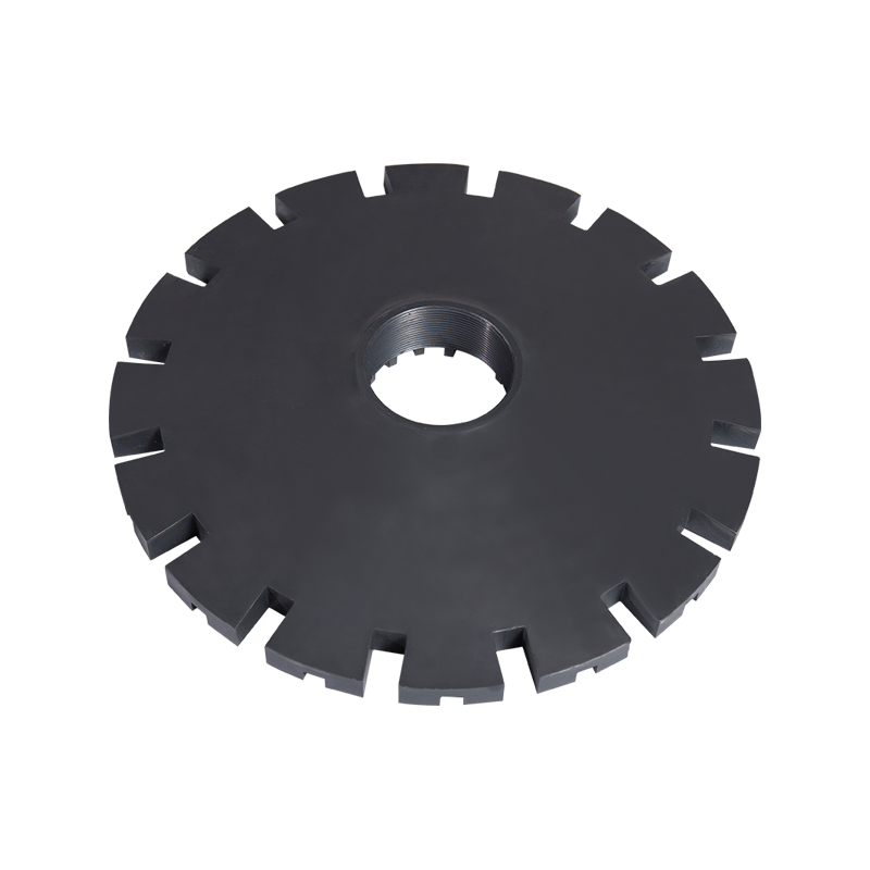
The rotary degassing unit (RDU) consists of a motor drive, a shaft, and the degassing rotor at the tip. The silicon nitride rotor is typically a disc or impeller shape with a central bore for gas delivery and a series of radial or angled slots that break the incoming inert gas stream into fine bubbles as the rotor spins. The design of these slots — their number, angle, and depth — significantly affects bubble size distribution and therefore degassing efficiency.
When the rotor is submerged and spinning, inert gas is fed down through the hollow shaft and exits through the rotor's dispersion ports. The centrifugal action of the spinning rotor shears the gas into bubbles with diameters typically in the range of 1 to 5 mm. Smaller bubbles have a higher surface-area-to-volume ratio, which means more contact area between gas and melt per unit of gas used — directly improving hydrogen removal efficiency. A well-designed silicon nitride degassing rotor achieves a final hydrogen content below 0.10 ml/100g of aluminum, which is the threshold for most structural casting applications.
The Role of Rotor Speed and Gas Flow Rate
Rotor speed and gas flow rate work together to determine bubble size and distribution. Increasing rotor RPM generally produces finer bubbles, but too high a speed creates turbulence that pulls surface oxides into the melt — the opposite of what degassing is meant to achieve. Most silicon nitride rotor manufacturers recommend operating speeds between 300 and 500 RPM for ladle-based degassing units, with gas flow rates of 2 to 10 liters per minute depending on melt volume. The optimal combination is determined empirically for each furnace configuration and alloy type, using reduced pressure testing (RPT) or density index measurements to verify hydrogen levels.
Flux Injection Compatibility
Some rotary degassing systems simultaneously inject fluxing powders (typically chloride or fluoride-based) along with the inert gas to improve inclusion removal and dross separation. Silicon nitride degassing rotors are chemically resistant to the chlorine and fluorine compounds used in these flux mixtures, whereas graphite rotors experience accelerated erosion in the presence of reactive flux gases. This compatibility makes Si₃N₄ rotors the practical choice for combined degassing and fluxing operations where simultaneous hydrogen removal and inclusion flotation are required.
Key Specifications to Check When Buying a Silicon Nitride Degassing Rotor
Not all silicon nitride rotors are manufactured to the same standard. The ceramics industry uses several grades and processing methods for Si₃N₄, and the differences are significant in high-temperature applications. Here are the technical specifications that matter most when evaluating or sourcing a ceramic degassing rotor:
- Density and porosity: A high-quality silicon nitride rotor should have a sintered density of at least 3.20 g/cm³, close to the theoretical maximum of 3.44 g/cm³. Lower density indicates residual porosity, which weakens the part and creates pathways for molten metal infiltration under rotational stress. Ask suppliers for density certification on each production batch.
- Sintering method: Hot-pressed silicon nitride (HPSN) and sintered reaction-bonded silicon nitride (SRBSN) are the two most common forms used in degassing applications. HPSN offers higher density and strength but is more expensive and limited to simpler geometries. SRBSN allows more complex rotor profiles with reliable properties and is widely used for impeller-style degassing rotors with intricate gas channels.
- Flexural strength: Look for a minimum flexural strength of 700 MPa (measured by four-point bending per ISO 14704). Rotors operating at high RPM in turbulent molten metal experience real bending loads, and a component below this threshold is at higher risk of fracture failure during operation.
- Shaft connection type: Si₃N₄ rotors connect to the degassing shaft via a threaded, flanged, or pin-and-socket joint. Threaded connections in ceramics require precision manufacturing to avoid stress concentrations at the thread roots. Confirm that the thread geometry and tolerance match your degassing unit's shaft specification before ordering, as non-standard fits are a leading cause of premature rotor fracture.
- Surface finish and gas port geometry: The dispersion holes and slots on the rotor should be precisely machined with smooth internal surfaces to prevent gas turbulence at the exit point. Rough or inconsistent port geometry produces uneven bubble distributions, reducing degassing efficiency. Request dimensional drawings and surface finish specs (Ra value) from the supplier if quality-critical applications are involved.
- Thermal shock test certification: Some manufacturers test rotors by cycling them between ambient temperature and 800°C multiple times before shipment. Ask whether the supplier performs this qualification and whether a certificate of conformance is available. Thermal shock testing catches micro-cracked components before they reach your production line.
Industries and Applications That Use Silicon Nitride Degassing Rotors
Silicon nitride degassing rotors are used wherever molten aluminum quality is a critical production variable. The industries relying on them span from high-volume automotive casting to precision aerospace manufacturing.
Automotive Casting
The automotive sector is the largest consumer of degassed aluminum castings. Engine blocks, cylinder heads, pistons, transmission housings, and structural chassis components all require low-porosity, high-integrity aluminum that meets stringent mechanical property specifications. High-pressure die casting (HPDC) and low-pressure die casting (LPDC) operations run continuous production cycles where consistent melt quality directly affects scrap rate and part dimensional accuracy. Silicon nitride rotors are standard equipment in automotive foundries precisely because their long service life and consistent performance support the tight process control required at scale.
Aerospace Aluminum Components
Aerospace applications demand even tighter control over melt hydrogen content than automotive, with target levels often below 0.08 ml/100g. Structural airframe components, wing ribs, fuselage fittings, and turbine housings made from aluminum alloys like 2024, 6061, and 7075 are subject to fatigue loading where subsurface porosity initiates cracks. The precision of degassing achieved with a silicon nitride rotor, combined with its contamination-free operation, makes it well-suited to the traceability and quality documentation requirements of aerospace supply chains.
Secondary Aluminum Recycling
Secondary aluminum smelters process recycled scrap, which introduces significantly higher levels of hydrogen, oxides, and inclusions than primary aluminum. Degassing is therefore more intensive in secondary operations, with longer treatment cycles and higher gas volumes. Silicon nitride degassing rotors withstand this more demanding operating regime better than graphite alternatives, which erode especially quickly under extended treatment cycles and elevated flux injection rates common in recycling furnaces.
Continuous Casting and Rolling
In-line degassing units are used in continuous casting lines for aluminum sheet, foil, and billet production. In these systems, molten aluminum flows continuously past one or more rotating degassing rotors installed in a treatment vessel between the furnace and the casting station. The ceramic degassing rotor in this application must maintain consistent performance over extended uninterrupted runs — sometimes days or weeks — without replacement. The durability of silicon nitride under these continuous-duty conditions makes it the material of choice for inline rotor systems from manufacturers such as Pyrotek, Foseco, and Almex.
Installing and Handling Silicon Nitride Degassing Rotors Correctly
Even the best silicon nitride rotor will fail prematurely if handled or installed incorrectly. Ceramic components require more care than metallic ones because they are brittle — they have high compressive strength but low tolerance for impact, bending, and uneven loading.
- Preheat before immersion: Never plunge a room-temperature silicon nitride rotor directly into molten aluminum. The thermal shock, even for a material rated for high ΔT, increases fracture risk significantly. Preheat the rotor above the melt surface using radiant heat from the furnace for at least 15 to 30 minutes before lowering it in. Some operations use a dedicated preheat station. This single practice is the most common factor separating operations with excellent rotor service life from those experiencing frequent failures.
- Inspect for micro-cracks before installation: Visually inspect every rotor before mounting it. Use dye penetrant inspection (DPI) or liquid penetrant testing if visual inspection is inconclusive. A hairline crack invisible to the naked eye can propagate rapidly under operating stress and cause the rotor to fracture in the melt — contaminating the aluminum charge and creating a hazardous situation.
- Torque the shaft connection correctly: Over-tightening the threaded connection between the shaft and the Si₃N₄ rotor is a frequent cause of fracture at the thread root. Follow the manufacturer's torque specification — typically 10 to 25 N·m depending on thread size and rotor geometry — and use a torque wrench rather than estimating by feel.
- Check shaft alignment before operation: A misaligned shaft transmits bending moments to the rotor during rotation, which combined with the thermal and chemical loads of the melt, concentrates stress at the shaft-rotor interface. Verify shaft concentricity with a dial indicator before first use and after any maintenance on the drive unit.
- Avoid contact with furnace walls and ladle edges: Train operators to lower the degassing unit into the center of the melt, away from refractory walls. Contact between the spinning rotor and a hard surface — even brief — can chip or crack the ceramic. Keep a minimum clearance of 50 mm between the rotor and any furnace surface during operation.
Evaluating the Total Cost of Ownership for Si₃N₄ Rotors
The upfront price of a silicon nitride degassing rotor is typically 3 to 6 times higher than a comparable graphite rotor. This purchase price gap leads some operations to default to graphite without running a full cost comparison. When total cost of ownership (TCO) is calculated properly — including replacement frequency, labor, downtime, and melt quality impact — silicon nitride consistently delivers lower cost per ton of aluminum processed.
Consider a typical high-volume foundry processing 200 tons of aluminum per month. A graphite rotor might last 3 to 4 weeks before requiring replacement, resulting in 12 to 16 rotor changes per year, each requiring furnace downtime and technician labor. A silicon nitride rotor in the same application might last 6 to 12 months, cutting replacement events to 1 to 2 per year. Over a 12-month period, even if each Si₃N₄ rotor costs five times more than graphite, the reduction in replacement frequency, labor cost, and production interruptions produces net savings of 30 to 60% depending on operational specifics.
There is also a melt quality dimension to the cost calculation. Graphite rotor degradation introduces fine carbon particles into the melt if the rotor deteriorates unexpectedly. These inclusions can cause casting defects that result in scrapped parts — a cost that is difficult to quantify per rotor but is very real in quality-sensitive production. Silicon nitride's non-reactive, non-shedding character under normal operating conditions eliminates this contamination risk entirely, which has measurable value in aerospace and automotive quality systems where inclusion-related scrap is tracked and penalized.
Troubleshooting Common Problems with Ceramic Degassing Rotors
Even well-maintained silicon nitride rotors encounter issues. Recognizing the symptoms of common problems early allows corrective action before a full rotor failure or a batch of substandard castings reaches inspection.
Insufficient Hydrogen Removal Despite Correct Parameters
If density index measurements show hydrogen levels above target even when rotor speed and gas flow are set correctly, the most common causes are partially blocked gas ports on the rotor and a gas supply leak upstream of the rotor. Remove the rotor after cooling and inspect the dispersion holes for aluminum oxide plugging — a common issue when the rotor is left in the melt after the unit stops rotating. Blow compressed air through the gas channel to confirm unobstructed flow before reinstalling.
Visible Rotor Erosion or Pitting
Surface erosion on a silicon nitride rotor is unusual under normal conditions but can occur if the rotor is used with highly aggressive flux mixtures at concentrations beyond the supplier's recommendation, or if the melt contains elevated levels of alkali metals (sodium, calcium) from contaminated scrap. If erosion is observed, reduce flux concentration and review scrap input quality. Severe erosion that changes the rotor's geometry affects bubble distribution and should be treated as a reason for replacement, even if the rotor is otherwise intact.
Rotor Fracture During Operation
Fracture of a silicon nitride degassing rotor during operation is a serious event that requires the melt to be inspected and potentially scrapped. The most frequent causes are thermal shock from insufficient preheating, overtorqued shaft connection, misaligned shaft, and impact against furnace walls. Post-failure investigation should examine all of these factors before the replacement rotor is put into service. Review the fracture surface: a fracture originating at the shaft thread indicates over-torque or stress concentration; a fracture through the impeller face suggests thermal shock; a fracture at the outer diameter suggests impact damage.
Hot Products


Contact Us for Quotes and Prices!
Just let us know what you want, and we will get in touch with you as soon as possible!
We will continue to develop and produce more advanced ceramic materials for the aluminum processing industry.
Scan the Mobile QR code
Contact
 +86-18501518842 / +86-13587222672
 +86-0572-2926332 / 2926337
 +86-0572-2926335
 [email protected] / [email protected] / [email protected]
 No.11 Building, South Taihu High-tech Intelligent Manufacturing Industrial Park, Wuxing District, Huzhou City, Zhejiang, China
Copyright© 2024 Zhejiang Shangguijuli Special Material Technology Co., Ltd. All Rights Reserved. Ceramic Material Supplier
